LCD Repair
Jump to navigation
Jump to search
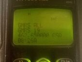
HT1550 XLS Display Repair
This is the guide that I followed on repairing a failing LCD Dot Matrix display on my HT1550-XLS UHF R2 radio. These WARIS portable models are highly desirable and are great radios. The custom Samsung made 4 line LCD Dot Matrix used in the HT1550XLS is discontinued and apparently unobtanium. If you can find a NOS or good used one it will cost as much as an entire eBay radio. I took the gamble to attempt to repair it knowing that I could break it very easily. I could learn from the experience and share this info with you!!
Credit
I followed a guide found online at the link below as the inspiration for this repair. Top shelf tips!
Step 1: Disassembly
- I won't cover destuffing the radio or getting down to the LCD. You should be able to find several examples of destuffing and disassembly on YouTube to get you to the guts of the radio or device you are working on.
- When you get down to the LCD board itself you have to peel off a protective sheet from the PCB side of the assembly. Then you will have access to the six (6) LED backlight solder points that connect the rear PCB to the glass LCD display itself. Unsolder these 6 connections carefully.
- Once you unsolder the backlight, carefully flip the PCB and glass LCD away from each other using the micro-ribbon flex cable as a hinge. You are now fully disassembled and ready to begin the actual repair procedure.
- According to Ben's article, the failure point is the connection of the flex cable to the PCB, not the flex cable to the LCD (thank goodness..) Let's resolder it!!
Step 2: LCD flex cable re-soldering
- This cable is of a plastic film of some sort. It appears to be able to withstand heat enough to melt solder but will surely have a melt point that causes damage. Finding that sweet temperature spot can be a risky undertaking.
- USE A DRY IRON TIP!!! No flux, no solder.
- I tried using the low (400`F) setting recommended in the guide linked but even using something as thin as a post-it note I was not able to achieve the melt point of the solder used to allow the connections to reestablish.
- The outermost 4-5 circuits on the ribbon flex cable were not connected to a trace on the PCB. I used this small unused area of the ribbon flex cable to test heat settings and how much damage a direct contact with the soldering would cause.
- After experimenting with temperature on my Weller iron and found that I could go up to ~480'F and not melt the material that the flex cable is made of in short 2-3 second contact using direct iron contact (no silicone or paper head dispersion layer). This seemed to achieve solder melt but avoid damage to the membrane itself.
- EXPERIMENT WITH YOUR HEAT SETTINGS BEFORE YOU COMMIT TO TOUCHING THE CABLE WITH YOUR IRON!!!!
- I took the gamble and used the clean, dry 480'F iron in a slow to moderate speed pass across the flex cable spending ~2 seconds over each solder joint. The pass was at the very last 1-2mm of the cable. I noticed very slight distortion of the flex cable membrane indicating heat transfer but no harmful membrane melting was observed. It did appear to melt the underlying solder of the cable connections though.
- I then moved up the cable ~3-4mm and made another pass slowly across the solder interface area noting the same minimal membrane heat distortion.
- That should be it. Hope it worked.....
Step 3: Test your repair
- I connected all the radio PCB boards back together outside the chassis of the radio and held a battery in place with a rubber band to power up the unit to ensure my repair was successful before reassembling the radio.
- IT WORKED!!!
- I then reassembled the radio and powered it up to a fully functioning LCD display.
- Thanks Ben at [P1Repair Blog] for the instructions on how to undertake this kind of repair!!


