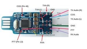
CM108 Interface
Jump to navigation
Jump to search
Notes on my CM108 adventures
- PTT and COS polarity (Active HI vs. Active LOW) are determined by your particular software and OS. If you cannot change them in software, you must use other discrete components to invert the signal. If your radio hangs in TX see if the condition persists with the USB unplugged. If it always shows COS active see if the condition persists with the radio unplugged. Beware of the maximum current draw on the PTT and COS and use a buffer stage BJT transistor or FET if required.
- TX and RX audio drive levels vary widely among radio equipment. You may have to adjust the levels in your software or possibly add physical attenuation or amplification depending on your application.
- I have used these exact boards in applications up to 50W and have experienced no RF interference issues. Your experience may vary and RF mitigation measures may be necessary.
- This exact setup is running my AllStar VHF nodes (Motorola CDM1250 and CM200) with no other components at all. Just wires connecting the appropriate pins on the radio to this CM108 board. Minor configuration in the Raspberry Pi software for GPIO polarity and audio levels were all that was required to get the node to function with the proper modulation and receive levels.
- I have experienced PTT hanging on the CM200 on power up and I beleive it has something to do with the PTT input being an active low state and being powered up with voltage on that pin. I need to invert the PTT programming in the radio and modify my simpleUSB.conf file to reflect the change to see if this remedies that problem.
