Difference between revisions of "ComPol FM SCA Receiver"
Jump to navigation
Jump to search
(Created page with "thumb|left thumb|left thumb|left") |
|||
| Line 1: | Line 1: | ||
| + | ==Description== | ||
| + | Work in progress... | ||
| + | |||
| + | ==LO== | ||
| + | Pierce/Colpitts style LO feeding MPS H10 VHF/UHF NPN<br> | ||
| + | *[[File:MPSH10-D datasheet.pdf|thumb]] | ||
| + | <br> | ||
| + | ==Monolithic FM IF - Harris CA3189E== | ||
| + | *The Harris CA3189E is a monolithic integrated circuit that provides all the functions of a comprehensive FM-lF system. The block diagram of the CA3189E includes a three-stage FM-lF amplifier/limiter configuration with level detectors for each stage, a doubly-balanced quadrature FM detector and an audio amplifier that features the optional use of a muting (squelch) circuit.<br> | ||
| + | **[[File:CA3189E datasheet.pdf|thumb]] | ||
| + | *The advanced circuit design of the IF system includes desirable deluxe features such as programmable delayed AGC for the RF tuner, an AFC drive circuit, and an output signal to drive a tuning meter and/or provide stereo switching logic. In addition, internal power-supply regulators maintain a nearly constant current drain over the voltage supply range of +8.5V to +16V. | ||
| + | <br> | ||
| + | ==Schematic== | ||
| + | *Rough schematic. Actual boards have revisions and modifications but seem to be fairly true to design. | ||
| + | **[[File:SCA-BA.pdf|thumb]] | ||
| + | *Capacitor tuning chart. The radio's tuned circuits have such a high Q that they will not tune the entire 88-108MHz FM band. Follow this chart for capacitor values across the band.<br> | ||
| + | **[[File:SCA-BA-Caps.pdf|thumb]] | ||
| + | <br> | ||
| + | ==Images== | ||
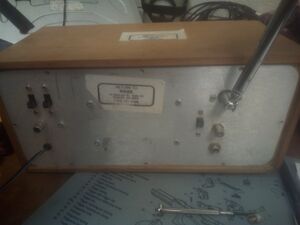
[[File:ComPol SCA FM Receiver Back.jpg|thumb|left]] | [[File:ComPol SCA FM Receiver Back.jpg|thumb|left]] | ||
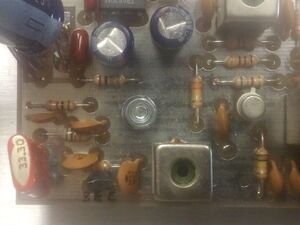
[[File:ComPol SCA FM Receiver LO and Mixer.jpg|thumb|left]] | [[File:ComPol SCA FM Receiver LO and Mixer.jpg|thumb|left]] | ||
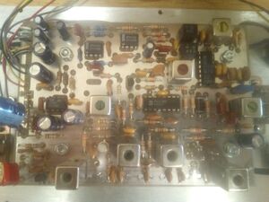
[[File:ComPol SCA FM Receiver Inside PCB.jpg|thumb|left]] | [[File:ComPol SCA FM Receiver Inside PCB.jpg|thumb|left]] | ||
Latest revision as of 20:33, 4 January 2021
Description
Work in progress...
LO
Pierce/Colpitts style LO feeding MPS H10 VHF/UHF NPN
Monolithic FM IF - Harris CA3189E
- The Harris CA3189E is a monolithic integrated circuit that provides all the functions of a comprehensive FM-lF system. The block diagram of the CA3189E includes a three-stage FM-lF amplifier/limiter configuration with level detectors for each stage, a doubly-balanced quadrature FM detector and an audio amplifier that features the optional use of a muting (squelch) circuit.
- The advanced circuit design of the IF system includes desirable deluxe features such as programmable delayed AGC for the RF tuner, an AFC drive circuit, and an output signal to drive a tuning meter and/or provide stereo switching logic. In addition, internal power-supply regulators maintain a nearly constant current drain over the voltage supply range of +8.5V to +16V.
Schematic
- Rough schematic. Actual boards have revisions and modifications but seem to be fairly true to design.
- Capacitor tuning chart. The radio's tuned circuits have such a high Q that they will not tune the entire 88-108MHz FM band. Follow this chart for capacitor values across the band.


