Difference between revisions of "HP BIOS Hacking"
| Line 58: | Line 58: | ||
===Open the file in a hex editor=== | ===Open the file in a hex editor=== | ||
I like using <code>HxD</code> or <code>wxHexEditor</code> or <code>Bless Hex Editor</code> in linux. Any of them will get you thru this process. <br> | I like using <code>HxD</code> or <code>wxHexEditor</code> or <code>Bless Hex Editor</code> in linux. Any of them will get you thru this process. <br> | ||
| − | <code>0F 00 00 00 00 00 00 00 24 00 00 00 00 00 00 00 | $......%....... | + | <code>0F 00 00 00 00 00 00 00 24 00 00 00 00 00 00 00 | $......%.......<br> |
| − | 00 00 00 00 00 00 00 00 00 00 00 00 00 05 1A 40 | .............%&f | + | 00 00 00 00 00 00 00 00 00 00 00 00 00 05 1A 40 | .............%&f<br> |
95 00 05 B4 06 CC C6 A2 36 40 42 21 36 40 41 21 | $.%@$.)#vFeDg%</code> | 95 00 05 B4 06 CC C6 A2 36 40 42 21 36 40 41 21 | $.%@$.)#vFeDg%</code> | ||
Revision as of 13:25, 10 May 2020
Using the Bus Pirate I have been successful in recovering several HP ProBook laptops that have BIOS Administrator passwords set. Below is a rough outline of the process.
Lets just assume that if you use any of these instructions on any of your own (or someone elses) equipment that you do so at your own demise. Kittens will die and babies will go hungry if you screw anything up. DO SO AT YOUR OWN RISK!!
Act One: Getting the Locked .bin out of the chip
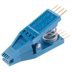
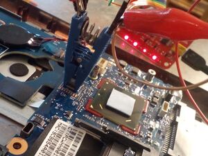
- Gain physical access to the BIOS chip. You may find access after removing the battery or an access panel on the bottom of the laptop. Some laptops do not have easy access to the BIOS IC. On the 6470b series you have to remove the back chassis to get the test clip on the chip even though there is a tiny access window right above the chip. I'm sure this is for assembly line provisioning or for large IT departments that have a backprobe type setup that fits in that tiny window.
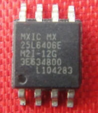
- Identify the manufacturer and model number of the IC. Mine was a MX25L6406E, YMMV.
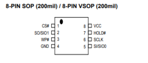
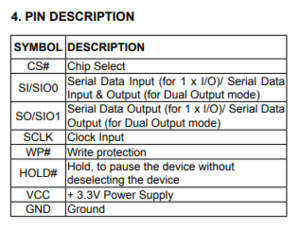
- Obtain a datasheet for your particular IC and determine the pinout for all the necessary pins required for flashing. This is super handy for correctly identifying that you have the correct IC on the board.
- My Connections
- The table below shows how a typical SPI flash chip (sitting in the center of the table) needs to be connected (NB: not all flash chips feature all of the pins below, but in general you should always connect all input pins of ICs to some defined potential (usually GND or VCC), ideally with a pull-up/down resistor in between).
| Description | Bus Pirate | Dir. | Flash chip | Dir. | Bus Pirate | Description | |||
|---|---|---|---|---|---|---|---|---|---|
| (not) Chip Select | CS | → | 1 | /CS | VCC | 8 | ← | +3.3v | Supply |
| Master In, Slave Out | MISO | ← | 2 | DO (IO1) | /HOLD (IO3) | 7 | ← | +3.3v | (not) hold (see datasheets) |
| (not) Write Protect | +3.3v | → | 3 | /WP (IO2) | CLK | 6 | ← | CLK | The SPI clock |
| Ground | GND | → | 4 | GND | DI (IO0) | 5 | ← | MOSI | Master Out, Slave In |
- Most SPI flash chips require a 3.3V supply voltage, but there exist some models that use e.g. 1.8V. Make sure the device in question is compatible before connecting any wires. NB: Some rather rare SPI flash chips (e.g. Atmel AT45DB series) have a completely different layout, please beware.
- Interesting findings:
- I have found that I was able to not connect the Vcc or Write Protect lines on any of the pins indicated and still get a successful read and write. I let the laptop's power supply provide the proper regulated voltage.
- If you use a genuine HP power supply and do not have the battery connected, it may detect the absence of the battery and disable the power supply after a few seconds.
- If you use an aftermarket supply with poor voltage regulation or noise, you may experience poor consistency in your reads and SHOULD NOT flash your BIOS over SPI if this is the case. A good quality aftermarket supply may not shut off with a missing battery and allow you to read and write if you can't insert your battery due to physical chip access blocking it.
- Interesting findings:
- NOW, LETS DO THE THING
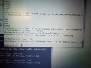
- Reading: The below command may work as-is. I have ran into a few models (EliteBook Revolve 810) that had multiple SPI devices on a shared bus that were detected upon running the below command. It will quit and put you back at a prompt if it detects multiple SPI devices. If so, you may have to specify the particular chipset in the command. Check the flashrom man page for details on how to do this.
$ flashrom -p buspirate_spi:dev=/dev/ttyUSB0,spispeed=1M -r flash.bin
- You will have to define your BusPirate device
/dev/whatEVERYou can probably find this in a quickdmesg - You must also define your output fine
-r flash.binThis will become important in the next step. - I never bothered trying faster SPI speeds as I was more concerned with consistent reads that speed.
- You will have to define your BusPirate device
- Use the above command (modified with your proper device and output filename) and start the first read. You should get a moderately verbose output from flashrom indicating that it has begun the read process and it will take quite a while (sometimes over 30 minutes) to extract the binary contents of the flash IC to your specified file.
- If the read was successful, change the output filename, something like
flash.1.binand do it again.
$ flashrom -p buspirate_spi:dev=/dev/ttyUSB0,spispeed=1M -r flash.1.bin
- Now, you should have two identical binary files if your reads were valid. Let's check the integrity of the two files against each other.
$ md5sum ./*.bin
- This command should indicate a md5 checksum for the two files that is IDENTICAL. If the checksum is identical, it means that you have read two perfect copies of the IC's contents with no errors.
- Just for good measure, do a third read with a new file name
flash.2.binand repeat themd5sumcheck to make sure you have three (3) identical files. - If you cannot get consistent reads.... DO NOT EVER WRITE!! You have been warned. My suggestion is to make sure you can get, at a minimum, THREE full binary reads that have the same checksum. If you cannot do this, you may have to resort to supplying the proper Vcc to the chip externally with proper regulation. DO SO AT YOUR OWN RISK.
Act Two: The actual h4x0ring of the thing
You now have three identical copies of the binary file that lives inside your target machine's BIOS IC. Now what? If you don't have three copies and still want to continue without making sure you have a pure copy, you are a true savage. Live your life. Now, here comes the fun part. It's almost like finding a needle in a hay stack. Except it doesn't look like a needle. It looks like this ´�ÌÆ¢6@B!6@A!�L|ªœ�D�p†�Ã�q82].2‰D. Fortunately someone much smarter and more talented than me has already figured out where the important bits lie. Let's walk thru this.
Open the file in a hex editor
I like using HxD or wxHexEditor or Bless Hex Editor in linux. Any of them will get you thru this process.
0F 00 00 00 00 00 00 00 24 00 00 00 00 00 00 00 | $......%.......

00 00 00 00 00 00 00 00 00 00 00 00 00 05 1A 40 | .............%&f

95 00 05 B4 06 CC C6 A2 36 40 42 21 36 40 41 21 | $.%@$.)#vFeDg%
Act Three: Put the cat back in the bag
A watched pot never boils.
Act Four: Clean up after surgery
Hopefully not much blood.
I hope to start a small library of BIOS binaries for the models I have recovered and the procedure used to recover a locked system.
HP ProBook & EliteBook
Information Sources
- General info about pinouts and flashrom
- Official flashrom Bus Pirate wiki
- flashrom man page(I guess no women allowed)
