Difference between revisions of "HP BIOS Hacking"
Jump to navigation
Jump to search
| Line 2: | Line 2: | ||
== BIOS Hacking == | == BIOS Hacking == | ||
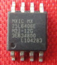
Using the [https://www.sparkfun.com/products/12942 Bus Pirate] I have been successful in recovering several HP ProBook laptops that have BIOS Administrator passwords set. Below is a rough outline of the process.[[File:25L6406e.jpg|thumb|right]] | Using the [https://www.sparkfun.com/products/12942 Bus Pirate] I have been successful in recovering several HP ProBook laptops that have BIOS Administrator passwords set. Below is a rough outline of the process.[[File:25L6406e.jpg|thumb|right]] | ||
| − | + | * Gain physical access to the BIOS chip and identify the manufacturer and model number of the IC. Mine was a 25L6406E, YMMV. | |
| − | + | * Obtain a datasheet for your particular IC and determine the pinout for all the necessary pins required for flashing. | |
| − | + | * Connections | |
| − | + | *The table below shows how a typical SPI flash chip (sitting in the center of the table) needs to be connected (NB: not all flash chips feature all of the pins below, but in general you should always connect all input pins of ICs to some defined potential (usually GND or VCC), ideally with a pull-up/down resistor in between). | |
{| style="border-collapse: collapse; border: 1px solid black;" cellpadding="5"; border="1" align="center" | {| style="border-collapse: collapse; border: 1px solid black;" cellpadding="5"; border="1" align="center" | ||
| Line 25: | Line 25: | ||
|- | |- | ||
|} | |} | ||
| − | + | * Most SPI flash chips require a 3.3V supply voltage, but there exist some models that use e.g. 1.8V. Make sure the device in question is compatible before connecting any wires. <small>NB: Some rather rare SPI flash chips (e.g. Atmel AT45DB series) have a completely different layout, please beware.</small> | |
---- | ---- | ||
I hope to start a small library of BIOS binaries for the models I have recovered and the procedure used to recover a locked system. | I hope to start a small library of BIOS binaries for the models I have recovered and the procedure used to recover a locked system. | ||
Revision as of 01:55, 10 May 2020
BIOS Hacking
Using the Bus Pirate I have been successful in recovering several HP ProBook laptops that have BIOS Administrator passwords set. Below is a rough outline of the process.
- Gain physical access to the BIOS chip and identify the manufacturer and model number of the IC. Mine was a 25L6406E, YMMV.
- Obtain a datasheet for your particular IC and determine the pinout for all the necessary pins required for flashing.
- Connections
- The table below shows how a typical SPI flash chip (sitting in the center of the table) needs to be connected (NB: not all flash chips feature all of the pins below, but in general you should always connect all input pins of ICs to some defined potential (usually GND or VCC), ideally with a pull-up/down resistor in between).
| Description | Bus Pirate | Dir. | Flash chip | Dir. | Bus Pirate | Description | |||
|---|---|---|---|---|---|---|---|---|---|
| (not) Chip Select | CS | → | 1 | /CS | VCC | 8 | ← | +3.3v | Supply |
| Master In, Slave Out | MISO | ← | 2 | DO (IO1) | /HOLD (IO3) | 7 | ← | +3.3v | (not) hold (see datasheets) |
| (not) Write Protect | +3.3v | → | 3 | /WP (IO2) | CLK | 6 | ← | CLK | The SPI clock |
| Ground | GND | → | 4 | GND | DI (IO0) | 5 | ← | MOSI | Master Out, Slave In |
- Most SPI flash chips require a 3.3V supply voltage, but there exist some models that use e.g. 1.8V. Make sure the device in question is compatible before connecting any wires. NB: Some rather rare SPI flash chips (e.g. Atmel AT45DB series) have a completely different layout, please beware.
I hope to start a small library of BIOS binaries for the models I have recovered and the procedure used to recover a locked system.
HP ProBook & EliteBook
Sources
- General info about pinouts and flashrom
- Official flashrom Bus Pirate wiki
- flashrom man page(I guess no women allowed)
